
P2240 Code: Bank 2 Sensor 1 Positive Current Circuit

P2240: Prove the Sensor Circuit
Identify Bank 2 Sensor 1 and separate pump-current control from heater and mixture faults.
DIAGNOSTIC FOCUS
- FAULT TYPE
- O2 Sensor Positive Current Control Circuit/Open, Bank 2 Sensor 1
- FIRST CHECKS
- Correct B2S1 location, connector and current-control wiring
The code does not establish catalyst failure, a heater-circuit defect or a confirmed rich or lean engine.
P2240 means O2 Sensor Positive Current Control Circuit/Open, Bank 2 Sensor 1. The code does not establish catalyst failure, a heater-circuit defect or a confirmed rich or lean engine. Save the full fault record, identify the reporting controller and use the current vehicle-specific procedure.
Save the original engine data, identify the exact upstream sensor and follow the manufacturer’s wideband circuit procedure. Do not apply a generic narrowband voltage test.
What Does the P2240 Code Mean?
P2240 describes an open or faulty positive current control circuit associated with oxygen sensor Bank 2 Sensor 1. In the cited Volkswagen reference, the monitor is explicitly associated with pump-current control. This is an electrical monitor within the sensor-control system, not a direct instruction to replace the catalyst.
Wideband oxygen-sensor operation is more complex than watching a conventional switching voltage. A controller regulates sensor functions and interprets the resulting electrical behavior. Test-terminal roles, reference values and permitted methods depend on the exact sensor and controller. A familiar-looking connector is not enough to identify which terminal can safely be tested.
Bank 2 and Sensor 1 must be located from the engine information. Avoid assumptions based on the side of the car or connector accessibility. Once the right sensor is identified, separate its current-control wiring from heater wiring, reference circuits and any genuine mixture problem shown by independent evidence.
Record the complete code, any suffix, reporting module and current/history status. The same short description does not establish a common circuit layout across vehicles.
A displayed lambda or fuel-trim value may be affected by an invalid sensor signal. It cannot, by itself, prove the engine is physically rich or lean while the current-control circuit is faulty.
Save available freeze frame and note engine temperature, load, sensor status, fuel-trim information and companion oxygen-sensor codes. A reset or disconnected connector can change the evidence before the cause is found.
P2240 Symptoms, Severity, and Driving Safety
Save the full oxygen-sensor and mixture code pattern, including present versus historical status.
The controller may handle invalid oxygen feedback differently by application; do not infer one universal fallback value.
Record the complaint, but verify actual fuel-control evidence before assigning it to a failed sensor.
If present, investigate misfire or other engine faults as well as the sensor circuit.
Shared supply, return or harness damage may affect several monitors. Map the actual wiring before combining the diagnosis.
A circuit fault can be stored even when the current driving impression appears normal. It still needs a valid diagnostic check.
Arrange prompt diagnosis and follow the owner manual warning instructions. Avoid heavy load if engine operation is abnormal or mixture control remains uncertain. The code itself cannot predict catalyst damage or establish a safe mileage allowance.
P2240 Causes and the Evidence That Separates Them
The following are possible diagnostic branches, not a ranking of failure rates. Their relevance depends on the installed wideband oxygen-sensor circuit. Begin with the branch identified by the OEM decision tree and the complete code pattern.
Connector damage
Heat, moisture, poor retention or a damaged terminal can interrupt a sensor circuit.
How to prove it: Inspect the identified B2S1 connector and use the approved terminal method.
Check firstHarness open or short
Exhaust heat or abrasion can affect an individual current-control conductor or adjacent circuits.
How to prove it: Trace and isolate the exact conductors according to the wiring diagram.
Check firstSensor internal defect
The sensor can fail an application-specific electrical or response check.
How to prove it: Confirm external circuits and use the specified wideband diagnostic procedure.
Verify directlyWrong replacement sensor
An incompatible part or altered connection can produce incorrect control behavior.
How to prove it: Verify the exact sensor application, connector and installation requirements.
Verify directlyShared reference or return fault
A common circuit defect may accompany several oxygen-sensor or control codes.
How to prove it: Compare the complete code pattern and test only the shared paths shown by the diagram.
Verify directlyController-side fault
An output-stage or control problem is a possible final branch after external evidence is resolved.
How to prove it: Follow the OEM decision tree before authorizing controller replacement or programming.
Final branchIf the warning followed sensor replacement, exhaust work or engine-harness repair, compare the timing with the original complaint. Recheck disturbed connections and part compatibility, but do not treat recent work alone as proof of causation. A component should earn replacement through a failed test.
Using UR1000 During P2240 Diagnosis
On supported vehicles, iCARZONE UR1000 retrieves accessible faults, available freeze frame and live data. Save the P2240 event before clearing it so the technician has the original evidence.
The official product page describes system diagnostics and bidirectional control. Confirm the exact VIN, controller, software and requested function before purchase. Every PID, active test or adaptation is not guaranteed on every vehicle.
On supported controllers, use UR1000 to preserve oxygen-sensor status, available lambda data, fuel trims and companion codes. Treat those as ECU-reported evidence. Physical circuit checks still require the correct equipment and the sensor-specific test method.
iCARZONE UR1000 Bidirectional Scan Tool with ECU Coding
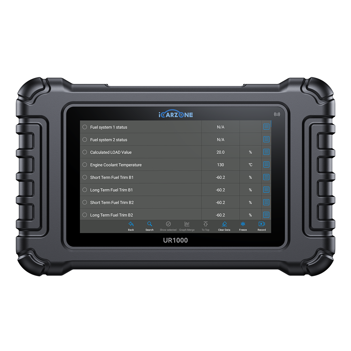
Keep the B2S1 circuit record and supported engine data together so a mixture symptom is not mistaken for proof of a failed catalyst.
Use the prescribed external equipment and current service information. A missing menu is a coverage question, not proof of failure. Price checked September 27, 2026; confirm the current offer on the product page.
How to Diagnose P2240 in 6 Steps
Use these six decisions alongside the VIN-specific procedure. Record conditions, measurements and comparison limits; never substitute another vehicle’s specification.
P2240 Quick Diagnostic Path
-
1
Save the complete original event
- Save all module faults, descriptions, suffixes, status and available freeze frame before clearing P2240. Preserve companion-code timing when investigating a shared condition.
- Document engine temperature, load, sensor status, fuel-trim information and companion oxygen-sensor codes. Note whether the warning preceded sensor replacement, exhaust work or engine-harness repair. Do not reproduce an unsafe symptom.
-
2
Locate the exact sensor and circuit
- Confirm the engine-bank diagram, sensor position and complete OEM description. Identify all relevant terminal functions.
- Do not treat passenger side, driver side or a generic wire color as a reliable bank or circuit identifier.
-
3
Review the full fault pattern
- Inspect heater, reference, supply, mixture and misfire records without merging their meanings.
- Establish which faults are current and which appeared together before using fuel-trim behavior to choose a repair.
-
4
Test the electrical path safely
- Inspect heat-exposed wiring and connector integrity, then perform the prescribed isolated or powered measurements.
- Do not use a test lamp, battery jumper or arbitrary ohmmeter test on a sensitive control terminal.
-
5
Evaluate the sensor and controller separately
- If external wiring passes, perform the sensor-specific test and only then follow any controller diagnostic branch.
- A rich/lean label from invalid feedback does not replace physical engine diagnosis. Correct independent fueling or misfire faults when their own evidence supports it.
-
6
Verify the repair under the right conditions
- Repeat the failed check, complete any required setup and compare the result with the original evidence. An extinguished lamp alone is not verification.
- Follow the OEM verification process and retain the final scan. Explain incomplete checks or remaining faults before releasing the vehicle.
How to Fix P2240 and Verify the Repair
Repair the proven harness path
Restore damaged wiring, terminals or connector sealing and protect the exhaust-area route.
Install the correct tested replacement
Replace a failed sensor only with the matching application and approved installation method.
Restore a shared circuit
Repair a demonstrated common reference or return defect, then retest every affected monitor.
Complete a proven control repair
Controller work requires the prescribed evidence, exact compatibility and required setup.
Diagnostic time
VIN-specific quoteRequest a quote that identifies the test needed to distinguish a harness or sensor defect from shared-circuit or controller trouble. A code scan alone is not completed diagnosis.
Wiring and access
VIN-specific quoteQuote proven terminal, harness and access work separately. Correct the cause of heat, abrasion or contamination to reduce repeat damage.
Proven component repair
VIN-specific quoteRequest the exact part, its failed test and required installation items. The correct service unit depends on the vehicle and demonstrated defect.
Setup and final verification
VIN-specific quoteInclude setup only when required, plus final verification. Local rates and taxes vary; these are alternative paths, not four automatic charges.
Ask which finding supports each proposed P2240 repair. Separate confirmed defects from conditional work and retain the original and final reports.
If a new sensor does not resolve the fault, compare the returning code and status. Recheck compatibility, disturbed wiring and the original test evidence before replacing another sensor or the catalyst.
P2240 OEM Differences and DIY Limits
The 2014 Volkswagen Touareg reference lists P2240 for Bank 2 Sensor 1 positive current control and describes pump-current monitoring. That supports the circuit distinction here. Its engine-specific numerical thresholds are not universal and are intentionally not transferred into this guide.
Confirm Bank 2 and the upstream Sensor 1 position from the engine diagram before testing any connector.
Separate current-control circuit integrity from heater operation and from actual combustion mixture.
The repaired current-control path and sensor response must pass the specified test, with independent mixture or misfire faults addressed separately.
Use the current service information for the exact engine and sensor technology. A conventional oxygen-sensor switching test, another bank’s pinout or an unrelated bulletin does not establish the correct procedure.
- Save the complete scan and warning text without clearing it.
- Record the conditions and service history accurately.
- Inspect only safely accessible areas under the specified power state.
- Follow the owner manual response to every active warning.
- Use qualified assistance when symptoms make operation unsafe.
- Do not jump, backfeed or force an unidentified circuit or actuator.
- Use the exact isolation procedure and specified test equipment.
- Leave required disassembly, learning or programming to equipped personnel.
Frequently Asked Questions About P2240
What does P2240 mean?
Is P2240 an oxygen-sensor heater code?
Does P2240 mean the catalyst is damaged?
Can I test it with a generic O2 voltage range?
Which side is Bank 2 Sensor 1?
Should I clear P2240 before diagnosis?
Can UR1000 help diagnose P2240?
What confirms a successful P2240 repair?
Sources and Technical Review Notes
- Volkswagen Touareg Quick Reference Specification Book, February 2014 — P2240 bank/sensor and pump-current distinction in the listed engine tables; no universal numerical thresholds.
- Bosch Mobility — Wideband lambda sensor — Pump-cell and measurement-cell architecture; not a universal vehicle pinout or test limit.
0 comments