
P2607 Code: Intake Air Heater B Circuit Low

P2607: Trace the Heater Circuit
A low circuit reading is an electrical clue, not a measurement of intake air temperature.
DIAGNOSTIC FOCUS
- FAULT TYPE
- Intake Air Heater B Circuit Low
- FIRST CHECKS
- Exact heater-B circuit, battery context and heat-damaged connections
Low does not mean cold intake air and does not establish which heater or control component failed.
P2607 means Intake Air Heater B Circuit Low. Low does not mean cold intake air and does not establish which heater or control component failed. Save the full fault record, identify the reporting controller and use the current vehicle-specific procedure.
Save the cold-start event and identify whether the OEM monitor concerns a control, supply or feedback path. Test that path with the specified high-current precautions.
What Does the P2607 Code Mean?
P2607 identifies a low condition in the intake air heater B circuit. The important word is circuit: the label does not report a low intake temperature or prove that the heater element is weak. The controller’s monitored electrical point and its expected response must come from the exact engine procedure.
An intake heating system may include a high-current load and a separate control or monitoring path. A low reading in one path does not automatically establish low current through the heater. Identify the relay or control-module arrangement, the monitored terminal and the specified power state before interpreting a measurement.
The B designation separates a circuit within the manufacturer’s system. It does not consistently identify the second relay, a particular engine bank or cylinder 2. Glow plugs, intake heaters and their control circuits are related starting aids but are not interchangeable components or fault definitions.
Record the complete code, any suffix, reporting module and current/history status. The same short description does not establish a common circuit layout across vehicles.
Keep controller feedback separate from independently measured supply voltage and load current. A relay command, a click or a visible preheat lamp does not establish that the intended heater path is healthy.
Save available freeze frame and note ambient and engine temperature, cranking behavior, preheat request and battery condition. A reset or disconnected connector can change the evidence before the cause is found.
P2607 Symptoms, Severity, and Driving Safety
Record the full fault text and all heater or supply codes.
The heating circuit may be relevant, but cranking speed, fuel and other engine conditions require separate evidence.
Avoid repeated extended attempts; record the temperature and follow the owner manual starting limits.
Note whether the condition changes as the engine warms. It does not prove an intake heater element failure.
A shared supply event may affect several modules or loads. Compare timing before replacing multiple parts.
A warm restart may not run the same heater request or monitor conditions as the original event.
Arrange diagnosis before relying on the vehicle in conditions where starting is already unreliable. Follow warnings and the owner manual. A stored circuit-low code does not establish a safe driving distance or justify repeated extended cranking.
P2607 Causes and the Evidence That Separates Them
The following are possible diagnostic branches, not a ranking of failure rates. Their relevance depends on the installed intake heater and control. Begin with the branch identified by the OEM decision tree and the complete code pattern.
Supply condition
A weak or interrupted supply can affect heater operation or its monitored path.
How to prove it: Test the specified battery and circuit conditions rather than judging from an unloaded reading.
Check firstControl wire short or damage
A low monitor state may originate in damaged control wiring.
How to prove it: Identify the monitored point and perform the OEM isolated circuit checks.
Check firstPoor return connection
A return-path defect may distort the expected electrical response.
How to prove it: Test the actual return under prescribed conditions; do not assume every case is a chassis-ground fault.
Verify directlyRelay or control-module defect
A command may fail to produce the intended response through the switching device.
How to prove it: Compare permitted command, input and output evidence with the exact circuit design.
Verify directlyHeater load problem
The heating element or its high-current connection may fail a specified load test.
How to prove it: Use the approved current or electrical method after safe isolation; no generic resistance threshold applies.
Verify directlyWrong part or installation
An incorrect relay, heater or connection arrangement may change monitored behavior.
How to prove it: Verify application and wiring after recent service before condemning the controller.
Final branchIf the warning followed battery, heater, relay or engine-harness service, compare the timing with the original complaint. Recheck disturbed connections and part compatibility, but do not treat recent work alone as proof of causation. A component should earn replacement through a failed test.
Using UR1000 During P2607 Diagnosis
On supported vehicles, iCARZONE UR1000 retrieves accessible faults, available freeze frame and live data. Save the P2607 event before clearing it so the technician has the original evidence.
The official product page describes system diagnostics and bidirectional control. Confirm the exact VIN, controller, software and requested function before purchase. Every PID, active test or adaptation is not guaranteed on every vehicle.
Use supported engine data to preserve heater requests, available status information and the cold-start context. UR1000 does not replace a suitable current clamp or prescribed electrical equipment, and it does not guarantee an intake-heater active test for every engine.
iCARZONE UR1000 Bidirectional Scan Tool with ECU Coding
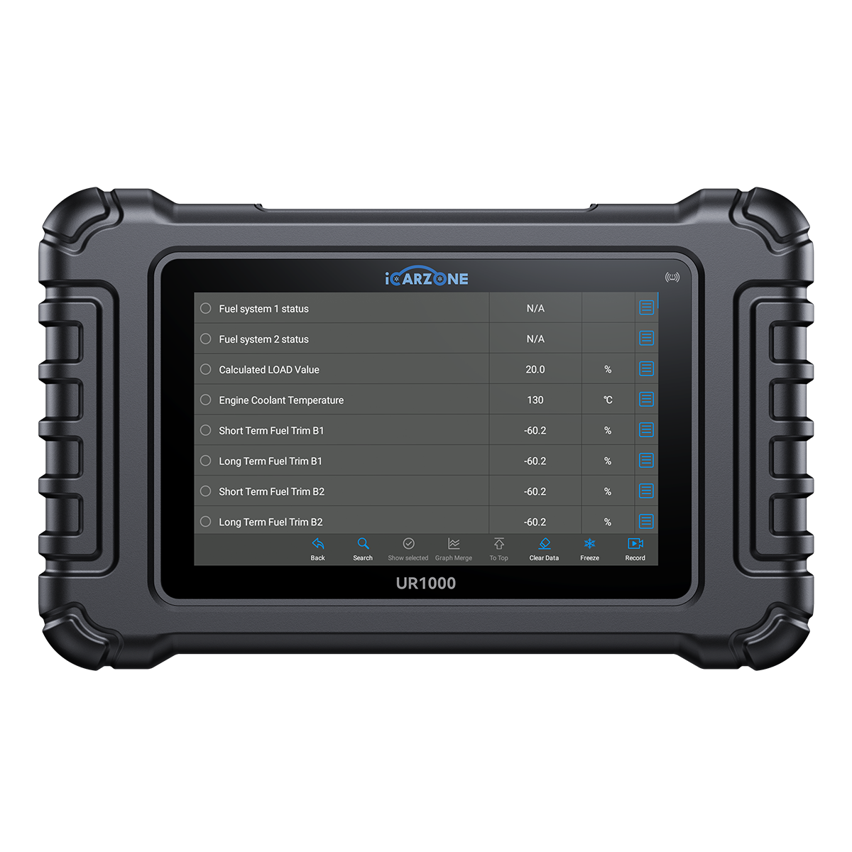
Save the heater request and fault timing while controlled electrical tests establish which part of the B circuit is actually low.
Use the prescribed external equipment and current service information. A missing menu is a coverage question, not proof of failure. Price checked September 27, 2026; confirm the current offer on the product page.
How to Diagnose P2607 in 6 Steps
Use these six decisions alongside the VIN-specific procedure. Record conditions, measurements and comparison limits; never substitute another vehicle’s specification.
P2607 Quick Diagnostic Path
-
1
Save the complete original event
- Save all module faults, descriptions, suffixes, status and available freeze frame before clearing P2607. Preserve companion-code timing when investigating a shared condition.
- Document ambient and engine temperature, cranking behavior, preheat request and battery condition. Note whether the warning preceded battery, heater, relay or engine-harness service. Do not reproduce an unsafe symptom.
-
2
Identify the monitored electrical point
- Obtain the engine’s heater diagram and full fault definition, including any suffix.
- Separate high-current supply from command and feedback terminals. Do not assume the label names the same terminal on every engine.
-
3
Inspect battery and connection context
- Check the documented starting complaint, shared supply codes and visible signs of heating or damage.
- A damaged high-current connection needs safe isolation before handling; do not simply tighten an energized terminal.
-
4
Measure control and supply separately
- Follow the specified load, voltage-drop, current or isolated circuit tests using appropriately rated equipment.
- Do not bridge a relay or feed power into a controller output to see whether the heater gets hot.
-
5
Prove the relay, module or load branch
- Compare the requested heater state with the measured electrical response and the OEM decision tree.
- Select a repair from the failed test. A relay click or cleared lamp does not prove that the heater load and monitor both operate correctly.
-
6
Verify the repair under the right conditions
- Repeat the failed check, complete any required setup and compare the result with the original evidence. An extinguished lamp alone is not verification.
- Follow the OEM verification process and retain the final scan. Explain incomplete checks or remaining faults before releasing the vehicle.
How to Fix P2607 and Verify the Repair
Restore a proven supply defect
Correct the demonstrated battery, cable or connection issue and retest under the specified load.
Repair the monitored wiring
Restore damaged control or feedback conductors and protect the route from heat and abrasion.
Replace a tested switching device
Confirm the relay or module failure after its inputs and external load have been checked.
Repair a proven heater load fault
Install the correct heater or service assembly using its isolation, fitting and verification procedure.
Diagnostic time
VIN-specific quoteRequest a quote that identifies the test needed to distinguish a supply or control-wire issue from a relay, module or heater-load defect. A code scan alone is not completed diagnosis.
Wiring and access
VIN-specific quoteQuote proven terminal, harness and access work separately. Correct the cause of heat, abrasion or contamination to reduce repeat damage.
Proven component repair
VIN-specific quoteRequest the exact part, its failed test and required installation items. The correct service unit depends on the vehicle and demonstrated defect.
Setup and final verification
VIN-specific quoteInclude setup only when required, plus final verification. Local rates and taxes vary; these are alternative paths, not four automatic charges.
Ask which finding supports each proposed P2607 repair. Separate confirmed defects from conditional work and retain the original and final reports.
If the fault returns only during a cold start, a warm workshop test may have missed the original conditions. Compare the saved request, temperatures and electrical response before changing another component.
P2607 OEM Differences and DIY Limits
The official Autel reference supports P2607 as intake air heater B circuit low and distinguishes nearby open, high and performance labels. It does not identify a universal vehicle application, current threshold, terminal or heater location.
Use the engine diagram to identify heater B and distinguish its load wiring from control and feedback paths.
A low monitor value is not automatically low heater current or low intake air temperature.
Repeat the failed electrical test and the prescribed heater-cycle verification under the required temperature and request conditions.
The engine manufacturer’s current information must define which circuit the controller monitors and when it expects a particular response. This guide intentionally supplies no generic pinout, resistance or fuse rating.
- Save the complete scan and warning text without clearing it.
- Record the conditions and service history accurately.
- Inspect only safely accessible areas under the specified power state.
- Follow the owner manual response to every active warning.
- Use qualified assistance when symptoms make operation unsafe.
- Do not jump, backfeed or force an unidentified circuit or actuator.
- Use the exact isolation procedure and specified test equipment.
- Leave required disassembly, learning or programming to equipped personnel.
Frequently Asked Questions About P2607
What does P2607 mean?
Does circuit low mean the intake air is too cold?
Is heater B the same as glow plug number 2?
Can a weak battery cause P2607?
Can I jump the heater relay to test it?
Should I clear P2607 before diagnosis?
Can UR1000 help diagnose P2607?
What confirms a successful P2607 repair?
Sources and Technical Review Notes
- Autel official diagnostic code reference — P2607 wording and neighboring heater-code distinctions only; no universal circuit or testing specification.
0 comments