
P0338 Code: Crank Sensor A Circuit High

P0338: Trace the Signal First
A high-input result does not establish a defective crankshaft sensor.
DIAGNOSTIC FOCUS
- FAULT TYPE
- Crankshaft position sensor A circuit
- FIRST CHECKS
- Event conditions, supply and signal path
High input describes the monitored electrical result, not high engine speed.
P0338 identifies crankshaft position sensor A circuit high input. Save the complete OEM wording and engine event. Establish the sensor design, power and signal path before testing; different sensor architectures do not share one resistance or voltage specification.
Preserve the full scan before clearing. A code identifies a monitor result, not a failed replacement part or a safe driving distance.
What Does the P0338 Code Mean?
The crankshaft position signal gives the engine controller information about crankshaft movement. P0338 is a high-input circuit label in the cited diagnostic-tool reference. It does not report that engine speed is too high, nor does it identify a mechanical crankshaft defect. The vehicle service information defines the actual monitored signal and the conditions that set the fault.
Sensor A is a logical designation that must be matched to the engine wiring and component information. Do not assume an arbitrary connector location, wire count or interchangeable sensor. An active sensor and a passive pickup require different test methods; a generic resistance check cannot establish the health of every design.
Preserve the circumstances of a no-start, stall or intermittent event. A normal signal after the vehicle cools or after a connector is moved does not disprove the earlier event. Conversely, a stored P0338 without a current symptom does not justify replacing the sensor. Compare module status, engine-speed information and the measured signal under the specified conditions.
P0338 identifies crankshaft position sensor A circuit high input.
Compare the actual signal at the approved points with supply, ground and the recorded operating state.
A failed sensor, a specific short direction and a damaged reluctor are not established by the base code alone.
P0338 Symptoms, Severity, and Driving Safety
A no-start or extended crank may accompany the concern. Record whether engine-speed data is available during the event.
A stall requires a safe stop and qualified assessment; do not repeatedly reproduce it in traffic.
Record whether the fault occurs during cranking, running, heat soak or after recent service.
Intermittent concerns require the saved event and status. A presently normal display does not disprove the original fault.
Save companion warnings and module faults to identify prerequisite problems and the event sequence.
Record recent battery, wiring, component and software work. Timing is evidence, not proof of causation.
Unexpected stalling or unreliable starting deserves prompt diagnosis. P0338 does not establish a safe driving distance or prove that a stored event will not recur.
P0338 Causes and the Evidence That Separates Them
Use the exact vehicle procedure to separate these possibilities. They are not a ranking of common failures; the base code cannot select the repair.
Signal-path fault
A wiring or connection problem can produce an unexpected high monitored input. The precise effect of an open, short or missing ground depends on the installed architecture.
How to prove it: Use the VIN diagram and approved measurements to identify the failed path; do not assume every high-input code means a short to battery.
Check firstSensor or supporting supply
A sensor cannot be judged independently of the required power, ground and operating conditions. Replacing it without checking those prerequisites can leave the fault unchanged.
How to prove it: Establish the specified supply and ground and compare the sensor output using the OEM method. Do not apply battery voltage to a signal terminal.
Check firstInstallation or target relationship
Recent engine work, incorrect installation or a target-related concern may affect the signal on applicable designs. The electrical high label does not itself prove target damage.
How to prove it: Inspect routing, fitment and any required gap or target checks only as directed for this engine. Keep mechanical inspection separate from a proven electrical fault.
Verify directlySupporting supply or ground
A supporting electrical fault can affect several functions. Check companion codes and the VIN diagram before treating each stored code as a separate component failure.
How to prove it: Test the specified supply and ground under OEM conditions. Do not invent a universal voltage-drop or resistance limit.
Verify directlyInstallation or recent work
Review disturbed connections, installed parts and required setup when the fault follows service work. Timing alone does not prove causation.
How to prove it: Match installation and required setup to the VIN before repeating a reset.
Verify directlyController or software
Consider this branch after the required external checks. A bulletin for another application does not authorize programming this vehicle.
How to prove it: Confirm current OEM applicability, software and prerequisites. Record the required verification after any justified update.
Final branchDo not substitute a camshaft timing or correlation diagnosis for a crank-sensor circuit test merely because both involve engine position.
Using JU2000 During P0338 Diagnosis
On a supported vehicle, iCARZONE JU2000 can preserve accessible system faults, available freeze frame and relevant live data. Save a report before erasing the event.
JU2000 may preserve compatible engine-controller faults, available freeze frame and engine-speed data. An RPM display is useful context but cannot prove waveform quality or isolate a high-input circuit. Confirm controller access and any required data by VIN.
The official page describes full-system diagnostics and bidirectional controls on supported applications. Exact controller access, PIDs, active tests and routines depend on the VIN and software. A general feature does not prove support for this procedure.
iCARZONE JU2000 All-System Bidirectional Scan Tool
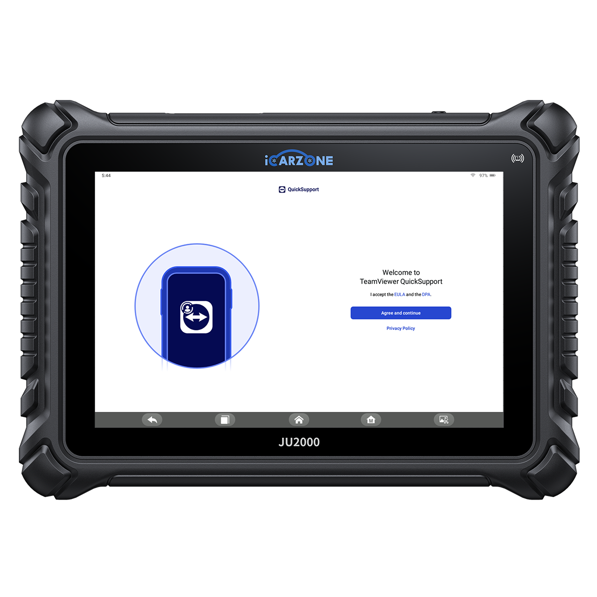
Preserve the crank or stall event and compare accessible engine data before clearing the original fault.
Confirm the exact vehicle and required function with iCARZONE before purchase. Use OEM-required equipment where specified. Scanner data does not replace physical measurement or remove active-test safety prerequisites.
How to Diagnose P0338 in 6 Steps
Preserve evidence, identify the application and follow its diagnostic branches. Resolve a failed prerequisite before moving to a more intrusive test.
P0338 Quick Diagnostic Path
-
1
Preserve the complete event
- Save the full OEM wording, suffix, module, active/history status and available freeze frame. Record operating conditions, warnings and recent work.
- Keep companion codes. Missing scanner access is a tool limitation, not proof of vehicle failure.
-
2
Identify the circuit and original event
- Match the VIN, engine, reporting controller and full descriptor to current service information. Record companion position, supply and network codes before selecting the diagnostic branch.
- Determine whether the concern occurs during cranking or running. Match sensor A to the actual diagram rather than a parts-store photograph.
-
3
Inspect without losing the evidence
- With the engine in the specified safe state, inspect accessible routing, connector engagement and recent work. Photograph findings before moving a suspect connection.
- Use the proper terminal inspection method. A connector that appears intact externally can still require an OEM electrical test.
-
4
Compare supply and measured signal
- A qualified technician should check the specified power and ground and measure the relevant signal at approved points. Follow the required cranking or running state and equipment instructions.
- Compare findings before and after the suspected path. Do not invent a waveform amplitude, pin number or resistance limit to fit the code label.
-
5
Choose an evidence-supported repair
- Use current VIN-specific diagnostics and applicable bulletins. Ask which finding excludes the alternative branches before authorizing a part.
- Confirm required programming or learning and equipment support. A generic menu name does not establish an OEM capability.
-
6
Verify the original monitor and save the outcome
- Verify starting and the original operating condition using the OEM procedure, then save the final scan. Do not use a brief idle or code clearance as proof that an intermittent stall is repaired.
- Save the final scan and verification conditions. Distinguish command acceptance, code clearance, monitor completion and demonstrated repair. Compare returning faults before replacing another part.
How to Fix P0338 and Verify the Repair
Repair the proven electrical path
Correct the demonstrated connection, wiring or supply fault using the OEM repair method. Preserve routing and protection against heat and vibration.
Replace only a demonstrated failed component
If the diagnostic sequence establishes a failed sensor or target-related component, use the correct application part and required installation procedure.
Correct the demonstrated external condition
Repair the proven connection, installation or supporting path using the OEM method. Record the failed test and the correction.
Complete required setup and verification
Perform required setup with approved equipment and prerequisites, then verify the original monitor. Code clearance alone is insufficient.
Diagnosis
VIN-specific quoteAsk for a VIN-specific diagnostic quote identifying the checks and evidence included.
Parts and labor
VIN-specific quoteSeparate proven repairs from exploratory replacement. The code cannot price the required work.
Required procedures
VIN-specific quoteInclude programming, learning or fluid handling only where the repair requires it.
Verification
VIN-specific quoteSpecify how the original concern will be verified; check applicable warranty coverage separately.
A useful report states whether the signal itself failed, a supporting path failed or the fault remained intermittent. These are different outcomes, even when the MIL clears.
These are planning categories, not prices to add together. Obtain a local quote connecting each operation to a demonstrated fault and stating what remains uncertain.
P0338 OEM Differences and DIY Limits
The primary reference establishes the base high-input label. This guide does not claim an OEM recall, campaign or universal repair for P0338; no verified application-specific bulletin is used to select a replacement part.
Base code description only; thresholds and repair decisions require the exact engine procedure.
Compare the actual signal at the approved points with supply, ground and the recorded operating state.
Waveform and electrical checks may require equipment beyond a scanner. A supported RPM PID does not replace those checks.
For the actual vehicle, obtain the current monitor description, wiring and test sequence. Sensor design, signal interpretation and access vary. Apply any engine-specific bulletin only after matching its complete scope and symptom.
- Save the full code, module and available event data.
- Record warning messages and recent repair history.
- Check the owner manual before deciding whether to move the vehicle.
- Record the starting conditions and inspect visible routing only with the engine stopped and cool.
- Do not jumper unidentified terminals or bypass a monitored circuit.
- Do not open or probe a system without its OEM safety procedure.
- Do not probe unidentified terminals or perform live waveform work around moving parts without training.
- Do not use a clear-code result as proof that the cause is repaired.
Frequently Asked Questions About P0338
Does high input mean high RPM?
Should I replace the crank sensor immediately?
Can an ohmmeter test every crank sensor?
What if the vehicle starts normally now?
What should I save before clearing the code?
What should the repair estimate explain?
Can iCARZONE JU2000 diagnose and clear this fault?
Why can a code return after a part was replaced?
Sources and Technical Review Notes
- Snap-on diagnostic trouble-code reference — Base description only; not OEM monitor thresholds, pinouts or a repair authorization.
- Official iCARZONE JU2000 product page — Current product, price and image check; all vehicle-specific functions require separate confirmation.
0 comments