
P0658 Code: Actuator Supply Voltage A Circuit Low

P0658: Trace the Supply Branch
Identify which actuators share the circuit before judging the load or controller.
DIAGNOSTIC FOCUS
- FAULT TYPE
- Actuator Supply Voltage A Circuit Low
- FIRST CHECKS
- OEM branch assignment, companion codes, loaded supply and connected loads
A low actuator-supply result is not automatically a low battery or a failed control module.
P0658 means Actuator Supply Voltage A Circuit Low. A low actuator-supply result is not automatically a low battery or a failed control module. Save the full fault record, identify the reporting controller and use the current vehicle-specific procedure.
Save all module faults and identify supply A in the correct wiring diagram. Separate the upstream source, connections, connected loads and controller-driver behavior using the OEM test sequence.
What Does the P0658 Code Mean?
P0658 means Actuator Supply Voltage A Circuit Low. The controller detected a low electrical condition in the actuator-supply circuit assigned A. The letter identifies an OEM circuit grouping, not a cylinder, engine bank or a universal fuse location.
An actuator supply powers a controlled load or group of loads. It must not automatically be treated as a sensor reference circuit. A diagram is needed to establish the supply arrangement, switching strategy, connected devices and the location being monitored.
Low describes the monitored circuit condition. It does not establish whether the upstream source is low, a connection drops voltage, a load pulls the circuit down or the controller has disabled a branch. These possibilities require different evidence and repair decisions.
Record the complete code, suffix, reporting module and status. A short description does not establish a common circuit layout.
Compare the source, supplied branch and expected operating state. A low reading on an intentionally disabled output is not automatically proof of a short or a failed driver.
Save available freeze frame and note module identity, operating state, battery events, related actuator faults and recent electrical work. A reset or disconnected connector can change the evidence before the cause is found.
P0658 Symptoms, Severity, and Driving Safety
The controller may store P0658 with a system or engine warning. Keep the complete message and status.
A connected actuator may not operate normally; the specific device depends on the circuit grouping.
Multiple actuator codes can help map a shared branch rather than prove that every load failed independently.
The affected controller may restrict operation. The fallback response is application-specific.
Heat, vibration or a marginal connection may produce a low condition only under load.
Such symptoms require the actual module and circuit context; the code does not imply one universal driveability pattern.
Identify which functions depend on the affected supply and evaluate their actual behavior. The code alone cannot establish whether a trip is safe or predict a particular fallback gear or operating mode.
P0658 Causes and the Evidence That Separates Them
The following are possible diagnostic branches, not a ranking of failure rates. Their relevance depends on the installed actuator supply and controller-driver architecture. Begin with the branch identified by the OEM decision tree and the complete code pattern.
Upstream supply problem
The branch may lack a sound source because of a feed, protection device or connection fault.
How to prove it: Identify the source and test it under the prescribed state and load; do not infer a dead battery from P0658 alone.
Check firstHigh-resistance connection
A poor terminal, splice or return path can affect voltage when current flows.
How to prove it: Use the approved loaded voltage-drop test and inspect the exact route rather than relying on an unloaded reading.
Check firstHarness short or insulation damage
A damaged branch can pull the supplied circuit down or trigger protective behavior.
How to prove it: Follow the OEM isolation sequence and inspect chafing, heat and recent repairs.
Verify directlyFault in a connected load
An actuator or internal connection may overload a shared branch, depending on circuit design.
How to prove it: Map all attached loads and isolate them only by the prescribed power-state and test procedure.
Verify directlyDriver or protection-state issue
A controlled output may be disabled after another fault or may have an internal defect.
How to prove it: Distinguish commanded state and protection response from a driver failure after external checks.
Verify directlyWrong part or installation
An incompatible actuator, wiring error or disturbed connector can be relevant after service.
How to prove it: Confirm part application and circuit routing against the original configuration and service record.
Final branchIf the warning followed battery, actuator, harness or control-module work, compare the timing with the original complaint. Recheck disturbed connections and part compatibility, but do not treat recent work alone as proof of causation. A component should earn replacement through a failed test.
Using JU2000 MAX During P0658 Diagnosis
On a supported vehicle, iCARZONE JU2000 MAX can retrieve accessible module faults, available freeze frame and live data. Preserve the P0658 record before erasing anything. A saved report gives the technician a baseline instead of relying on a remembered warning message.
The official product page describes system diagnostics and bidirectional control. Confirm the exact VIN, controller, software and requested function before purchase. A product feature list does not guarantee every PID, active test, reset or adaptation on every vehicle.
Where supported, record actuator-supply status, relevant commands and companion faults across accessible modules. JU2000 MAX cannot perform a physical voltage-drop or load-current measurement. An active-test menu is useful only when coverage and the safe test conditions are confirmed.
iCARZONE JU2000 MAX All-in-One Diagnostic & TPMS Kit
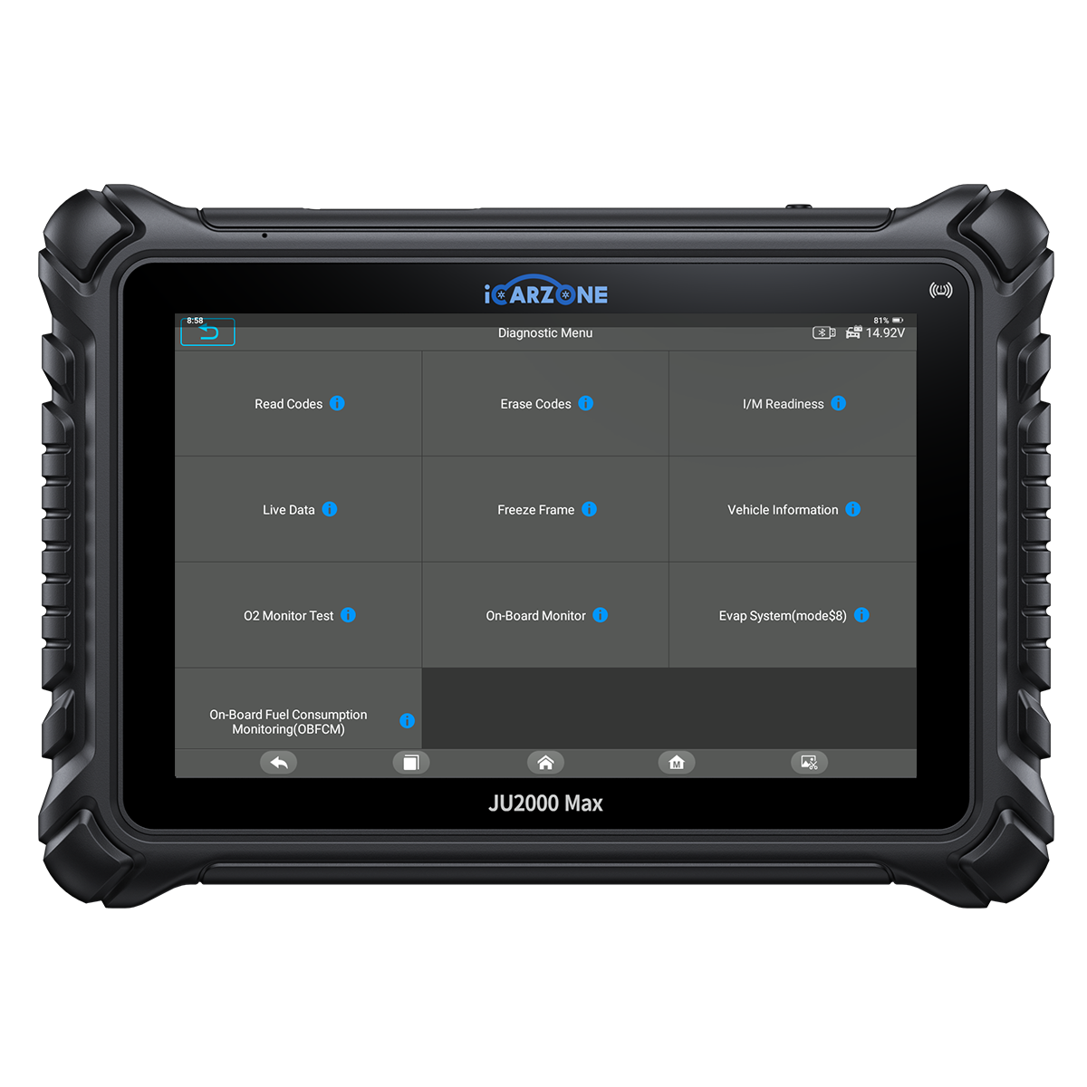
Capture shared-branch and actuator-code evidence before unplugging loads or clearing the event.
Use the scanner alongside the prescribed external test equipment and current service information. An unavailable menu is a coverage or access question, not proof that a component failed. Price checked October 8, 2026; confirm the current offer and vehicle coverage on the product page.
How to Diagnose P0658 in 6 Steps
This six-step sequence explains the decisions a diagnosis needs to resolve. It is not a substitute for the VIN-specific service procedure. Keep a record of the test conditions, measured results and comparison limits; do not fill a missing specification with a number from another vehicle.
P0658 Quick Diagnostic Path
-
1
Save the complete original event
- Record all modules' faults, full descriptions, suffixes, status and available freeze frame before clearing P0658. Save companion codes even when they seem unrelated; their timing may identify a shared supply, communication or operating-condition problem.
- Document module identity, operating state, battery events, related actuator faults and recent electrical work. Ask when the warning first appeared and whether it preceded battery, actuator, harness or control-module work. Do not recreate an unsafe symptom merely to collect a better graph.
-
2
Map the actuator-supply circuit
- Confirm the reporting controller and exact A assignment from current diagrams. Identify source, switching devices, return paths and all connected loads.
- Obtain test conditions and protection behavior. Do not assume that A names a particular fuse, solenoid or sensor on every vehicle.
-
3
Establish a valid electrical baseline
- Review supply, communication and actuator companion codes. Note whether the branch was commanded on or disabled when data was captured.
- Test the relevant power and ground paths under the specified conditions. An unloaded meter reading may not reveal a poor connection under operating current.
-
4
Separate wiring from connected loads
- Use the approved isolation sequence to determine whether a low branch condition follows wiring, one load or a shared connection.
- Respect power-off and connector-handling instructions. Do not backfeed the circuit, fit a larger fuse or disconnect loads randomly during operation.
-
5
Evaluate driver behavior after external proof
- When feeds, wiring and loads satisfy the required checks, follow the controller-driver and protection-state decision tree.
- Check applicable configuration or software guidance only after identifying the system. A low output while protection is active is not enough to justify module replacement.
-
6
Verify the repair under the right conditions
- Repeat the failed measurement or functional check. Complete only required setup or learning, then compare the result with the saved baseline.
- Follow OEM verification, retain the final scan and disclose incomplete tests. Diagnose any new symptom or code separately.
How to Fix P0658 and Verify the Repair
Restore the verified feed or return
Repair proven terminals, splices or supply connections using specified protection and repair methods.
Correct branch wiring
Repair the demonstrated short or resistance problem and remove the source of damage.
Replace a proven faulty load
Use the correct actuator or service assembly only after isolation and component tests establish failure.
Repair the confirmed driver branch
Apply required module or software work only after external checks, then verify every affected load and monitor.
Diagnostic time
VIN-specific quoteRequest a quote distinguishing an upstream feed, branch wiring, connected load and controller driver. A code read alone does not identify the replacement part.
Wiring and access
VIN-specific quoteQuote proven terminal, harness and access work separately. Correct the source of heat, abrasion or contamination.
Proven component repair
VIN-specific quoteAsk for the exact part, failed test and required supporting items. The correct service unit depends on the vehicle and defect.
Setup and final verification
VIN-specific quoteInclude learning, calibration or programming only when required. Labor, parts and access differ; these are alternative paths, not four automatic charges.
Ask the shop to connect each proposed repair to a finding and separate confirmed defects from conditional work. Keep the original and final reports.
If several actuator codes disappear after a shared repair, still verify each affected function. Clearing the code list does not show that the supply remains stable under its required load.
P0658 OEM Differences and DIY Limits
Audi’s archived A4/S4 reference tables distinguish P0657 actuator-supply A open, P0658 low and P0659 high. This supports the direction of the P0658 fault, but its application-specific thresholds and circuit details must not be generalized.
Map the actual actuator-supply grouping and responsible module rather than assuming A means a sensor reference.
Record the commanded state and compare source, branch and return measurements under the OEM conditions.
Repeat the failed loaded-circuit test, confirm the affected actuator functions and complete the applicable monitor checks without returning related faults.
Use current information for the exact vehicle to determine which controller and loads belong to supply A. A source document from another transmission or engine cannot establish a common voltage, connector position, fuse rating or repair for this code.
- Save the complete scan and warning text without clearing it.
- Record the conditions and service history accurately.
- Inspect only safely accessible areas under the specified power state.
- Follow the owner manual response to every active warning.
- Use qualified assistance when symptoms make operation unsafe.
- Do not jump, backfeed or force an unidentified circuit or actuator.
- Use the exact isolation procedure and specified test equipment.
- Leave required disassembly, learning or programming to equipped personnel.
Frequently Asked Questions About P0658
What does P0658 mean?
Is actuator supply A always five volts?
Does P0658 prove the battery is bad?
Should I unplug actuators until the code clears?
Is P0658 the same as P0642?
Should I clear P0658 before diagnosis?
Can JU2000 MAX help diagnose P0658?
What confirms a successful P0658 repair?
Sources and Technical Review Notes
- Audi A4/S4 Quick Reference Specification Book — Application-specific P0657/P0658/P0659 actuator-supply classifications; numeric limits not generalized.
- Tags: DTC iCARZONE JU2000 MAX OBD-II P0658
0 comments